In the second unit of Honors Engineering, we explored electronics and circuits. We also gained hands-on experience by physically building circuits.
- Voltage (V) is like water pressure in a river. It represents the force pushing electrons through the circuit, similar to how pressure pushes water through a pipe.
- Current (I) is like the flow rate of the river. It represents the actual flow of electrons in the circuit, just as the river's current is the flow of water.
- Resistance (R) is like obstacles or the narrowness of the river (rocks, constrictions, etc.). It represents anything that slows down the flow of electricity, similar to how rocks in a river impede water flow.
We started the unit by learning how electricity flows. We covered the three concepts that are needed to conceptualize electrical flow: current, voltage, and resistance. To better understand these concepts, we used a river as an analogy.
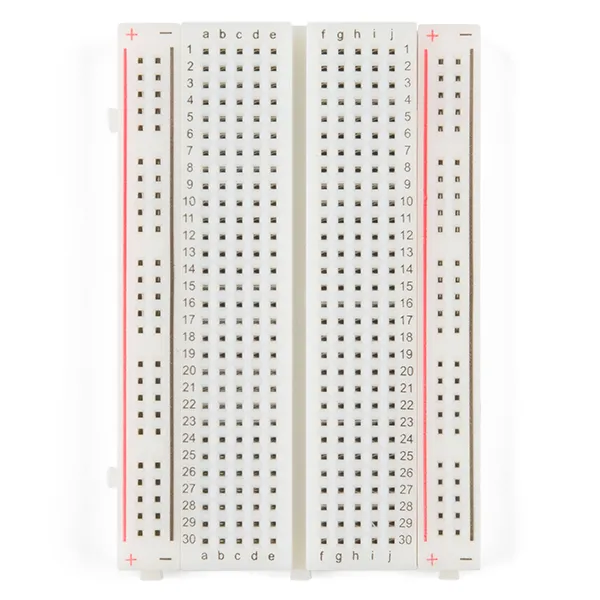
We also learned about an essential tool for building circuits: the breadboard. The breadboard is where we assembled our circuits. We discovered that each side of the breadboard has positive and negative rails that run along its length, providing power across the circuit. In the middle section, the rows are connected, meaning the terminals in each row are linked horizontally. This design allows us to prototype various important circuits efficiently.
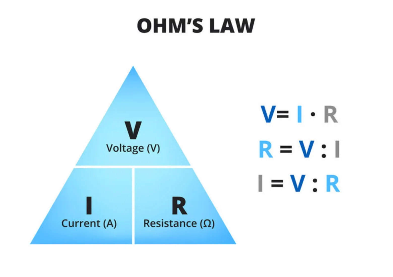
We then learned about Ohm's Law, which defines the relationship between voltage, current, and resistance. Ohm's Law states that voltage is the product of current and resistance ($V = I \times R$), meaning that voltage is directly proportional to the current flowing through a circuit for a given resistance. One practical application of Ohm's Law is preventing damage to components like LEDs. By understanding this relationship, we can ensure we don't use a resistor that is too small, which would allow too much current to flow through the LED and potentially burn it out.
Series and Parallel Circuits
We started with basic circuits: simple series and parallel designs used to power one or two LEDs.
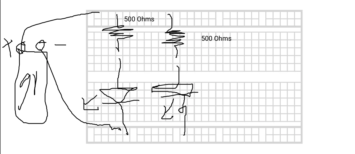
This is an example of a series circuit we built. The two LEDs and the two resistors are in series with each other. This means the sum of the voltages across the resistors should equal the battery voltage, and the current remains the same across all components because they are on a single path.
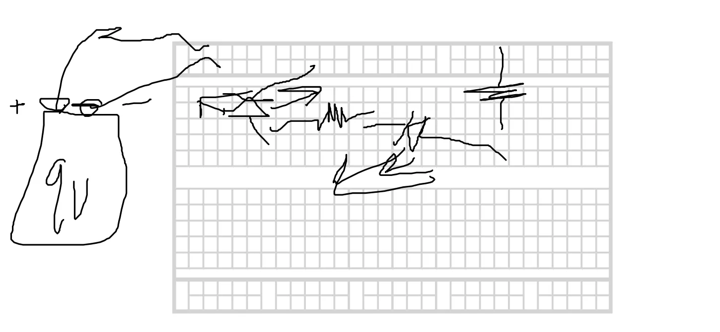
We then constructed a parallel circuit, meaning the two LED-resistor pairs were not in series but rather parallel to one another. In this configuration, the total current from the battery is split between the branches. Because each resistor-LED pair is connected across the battery, each branch receives the full battery voltage. Above is the schematic we drew for the parallel circuit.
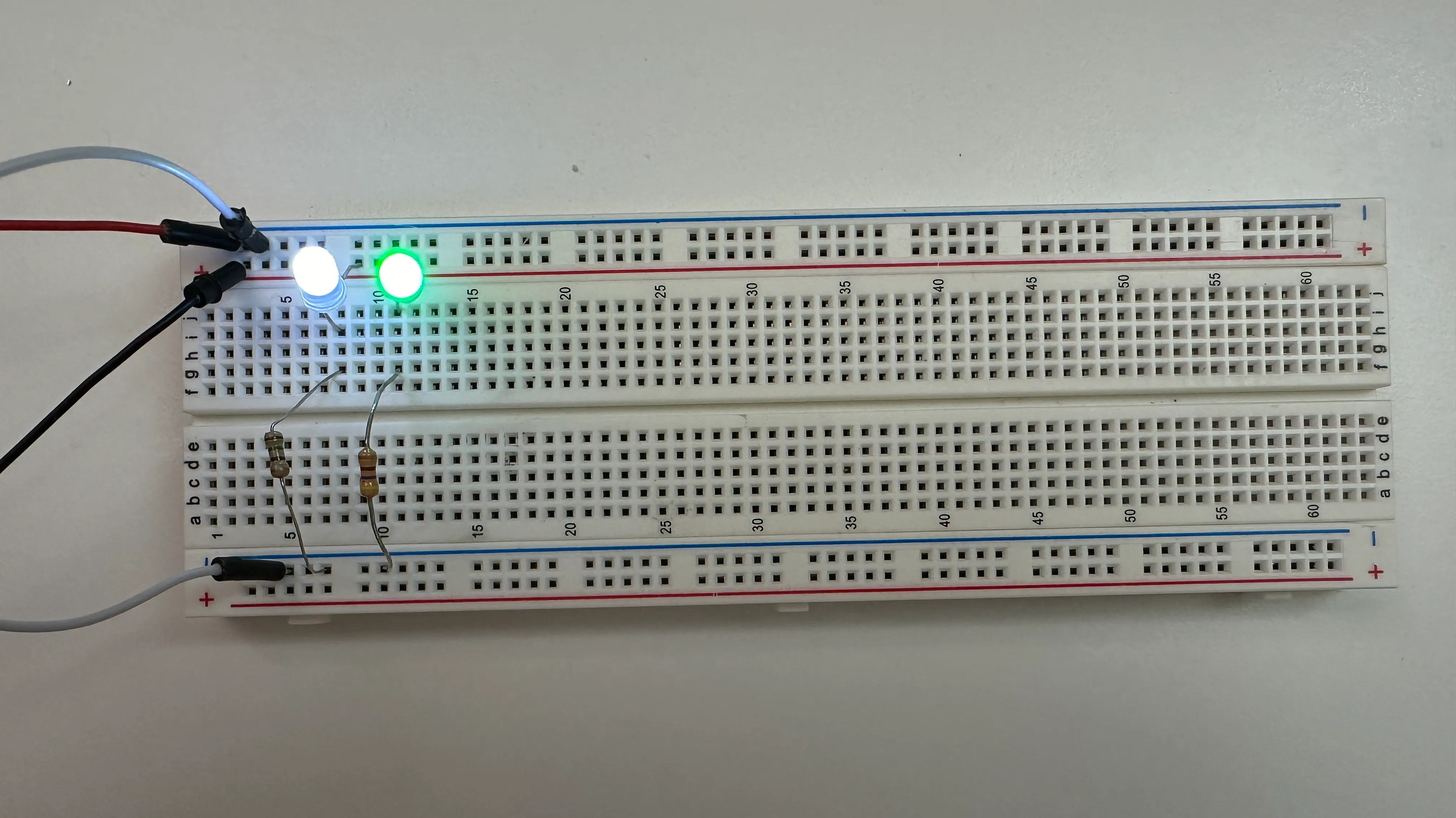
Below is a picture of my wired-up parallel circuit on a breadboard. You can see the two distinct channels for each LED. If you were to remove a resistor from one channel, it would only affect that specific LED, while the other channel would remain lit.
Nightlight Circuit
We then built a more complex circuit: a nightlight. The goal was to create an LED that turns on when it detects darkness and turns off when light is present. We used the following circuit diagram as our reference.
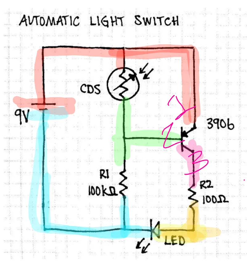
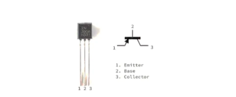
In this circuit, we were introduced to two new components: the CDS photoresistor and the transistor. While photoresistors are specialized, transistors are fundamental to almost all modern electronics. We learned how a transistor acts as a switch or amplifier. Here is the specific transistor we used in our build.
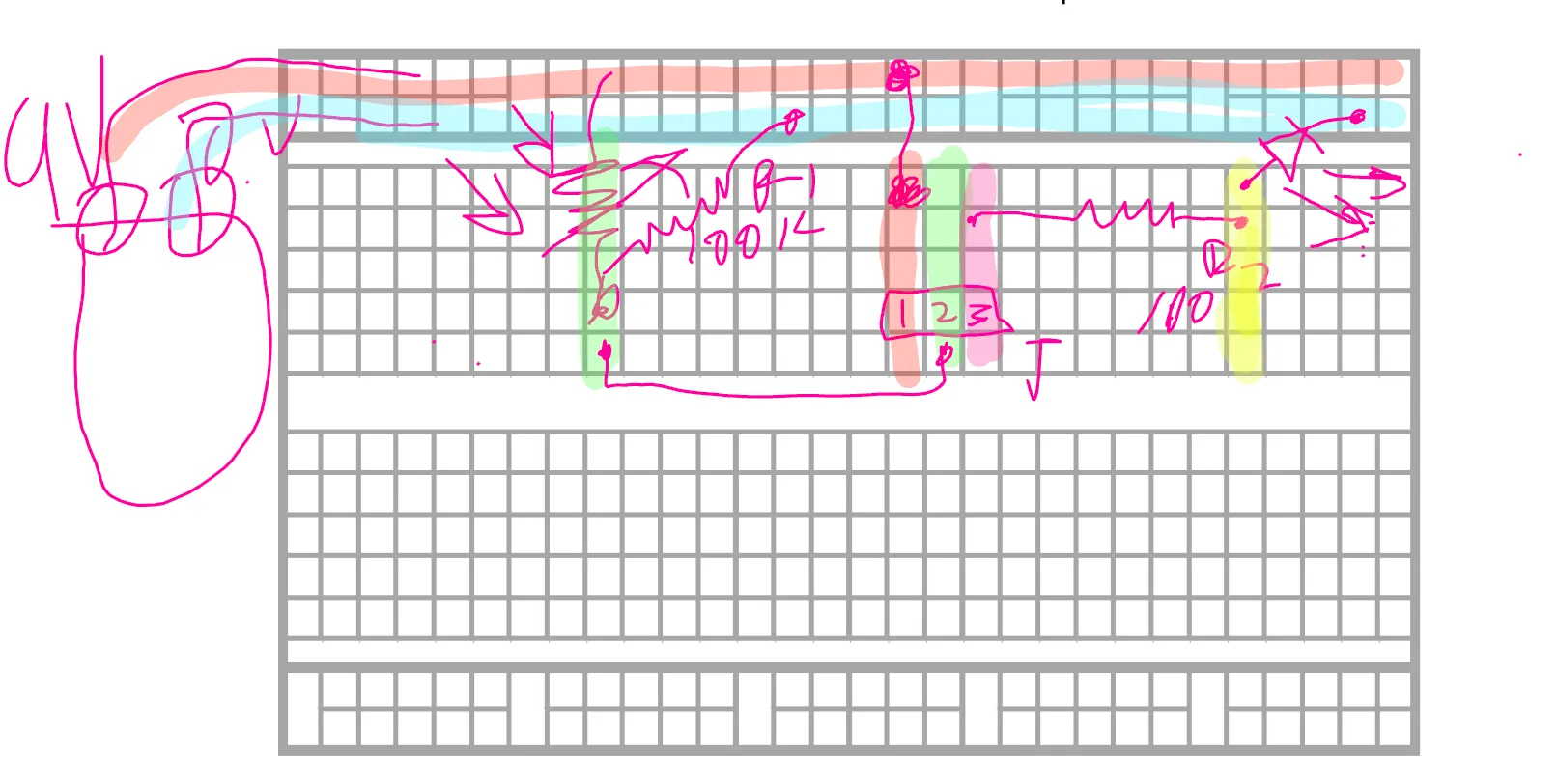
Before assembling the circuit, we needed to visualize the breadboard layout, as schematics often differ from the physical placement. We used the provided diagram to create a breadboard illustration. Here is the digital concept showing how the connections were planned for the final build.
We replicated the digital drawing onto the physical breadboard. Below is an image of my completed circuit. Note that some sections are blurred because I was using the breadboard for multiple projects simultaneously.
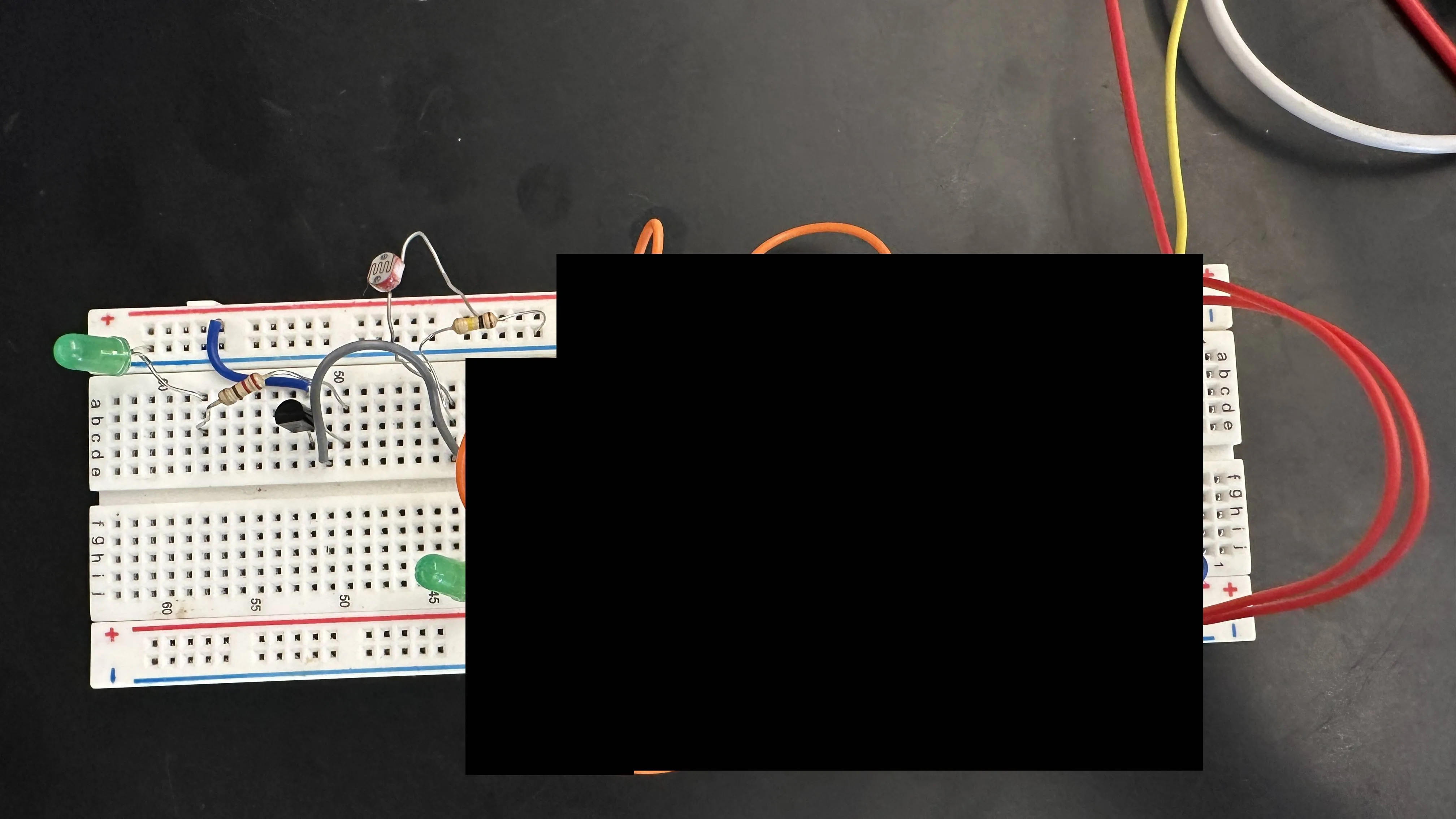
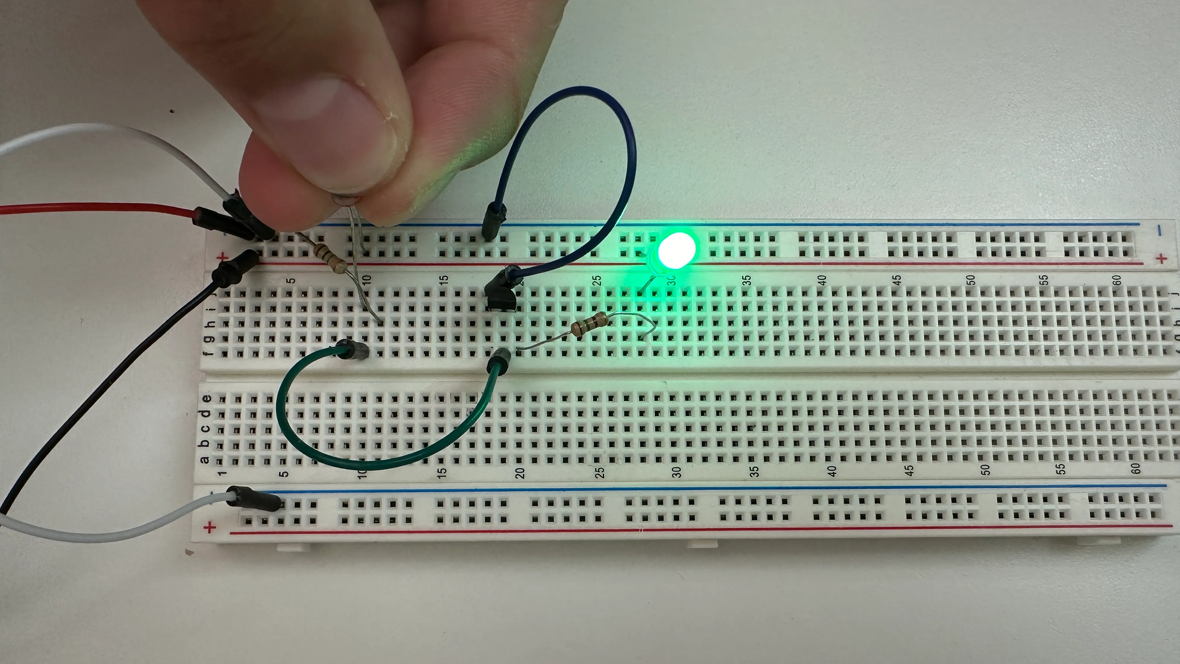
This image demonstrates the circuit in action: when I cover the photoresistor to simulate darkness, the LED illuminates exactly as expected for a nightlight.
Reflection
Overall, this unit was quite enjoyable. Since I already had some experience with electronics from a previous class, it served as a great review of the basics. Most of the tasks were straightforward due to my prior knowledge, though I did encounter some trouble getting the nightlight to work. One challenge was sourcing the correct parts, such as a 100k Ohm resistor. The primary issue, however, was using the wrong transistor; I initially grabbed a 2222 instead of the 3906 required. Because the 2222 has a different polarity, the LED functioned in reverse—turning on in bright light and off in the dark. Once I swapped it for the correct component, the circuit worked perfectly. I ended up helping several classmates troubleshoot similar issues, such as using incorrect resistor values.
Following that project, I attempted a more complex circuit: a blinking LED utilizing a 555 timer. I spent several class periods debugging it but could not get it to function. Despite rebuilding the circuit twice, the issue persisted. I suspect some of the components, perhaps the 555 timer itself, may have been faulty, though I am still looking for a definitive way to test that.