To finish off our Engineering class, we built a final project: a light sculpture. I built a disco ball hook.
The Idea
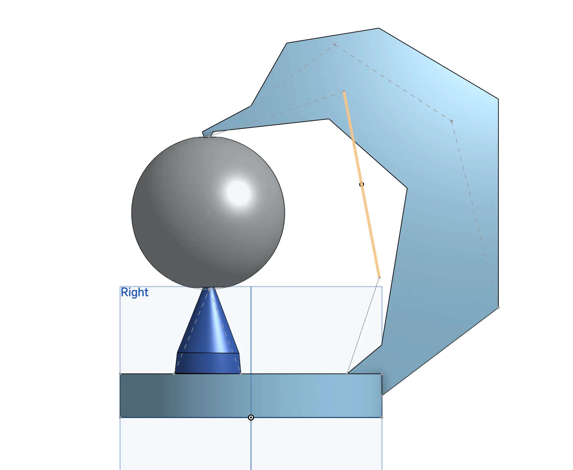
My idea for the disco ball hook was inspired by the floating disco balls seen in 1970s movies and the Las Vegas Sphere. For lighting, I wanted a hook that would go up and over a ball; my initial sketch can be seen on the right. The design includes a hook that loops over the ball and a cone that supports it from underneath. This ensures the ball is securely hooked. I also wanted to include LEDs that shine inside the ball and along the arm. My plan was to use a custom PCB along with translucent 3D-printed parts to achieve diffused lighting.
The CADing Process
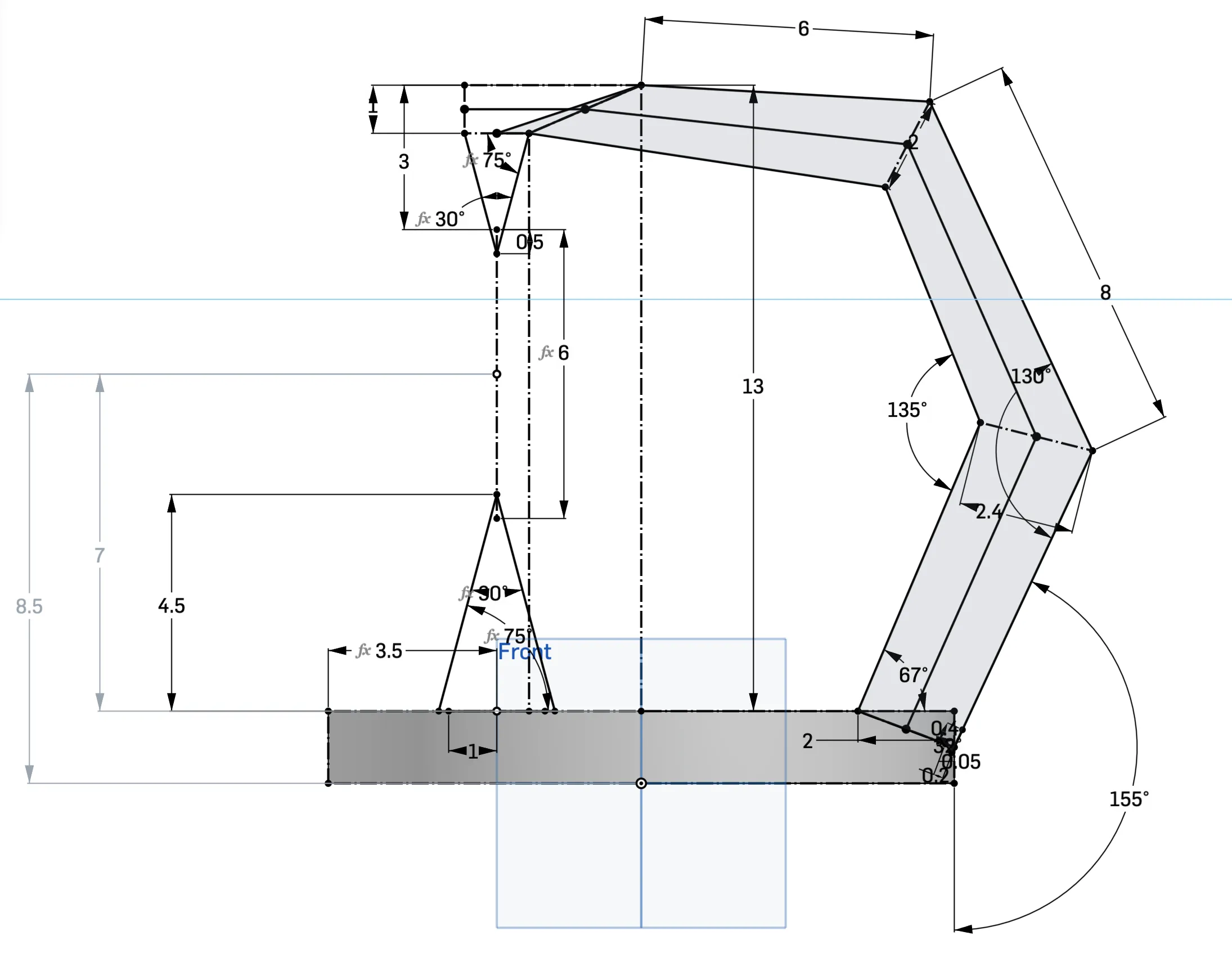
Overall, the CADing process was quite easy. I was already proficient with CAD before the class, and after the CADing unit, I felt very confident. I started by taking my initial idea and making a rough sketch in Onshape to plan everything out. I used one singular sketch that defined the entire project's scope. This sketch, seen on the right, defined the profile of my light sculpture; everything else in the model was based on this sketch. Another important step was designing the entire sculpture within a single Part Studio. This is how Onshape is designed to function, and it is what makes it unique compared to other CAD programs. Using one Part Studio allowed me to design the whole sculpture and ensure everything connected properly, rather than spending time on an assembly only to find that parts didn't fit.
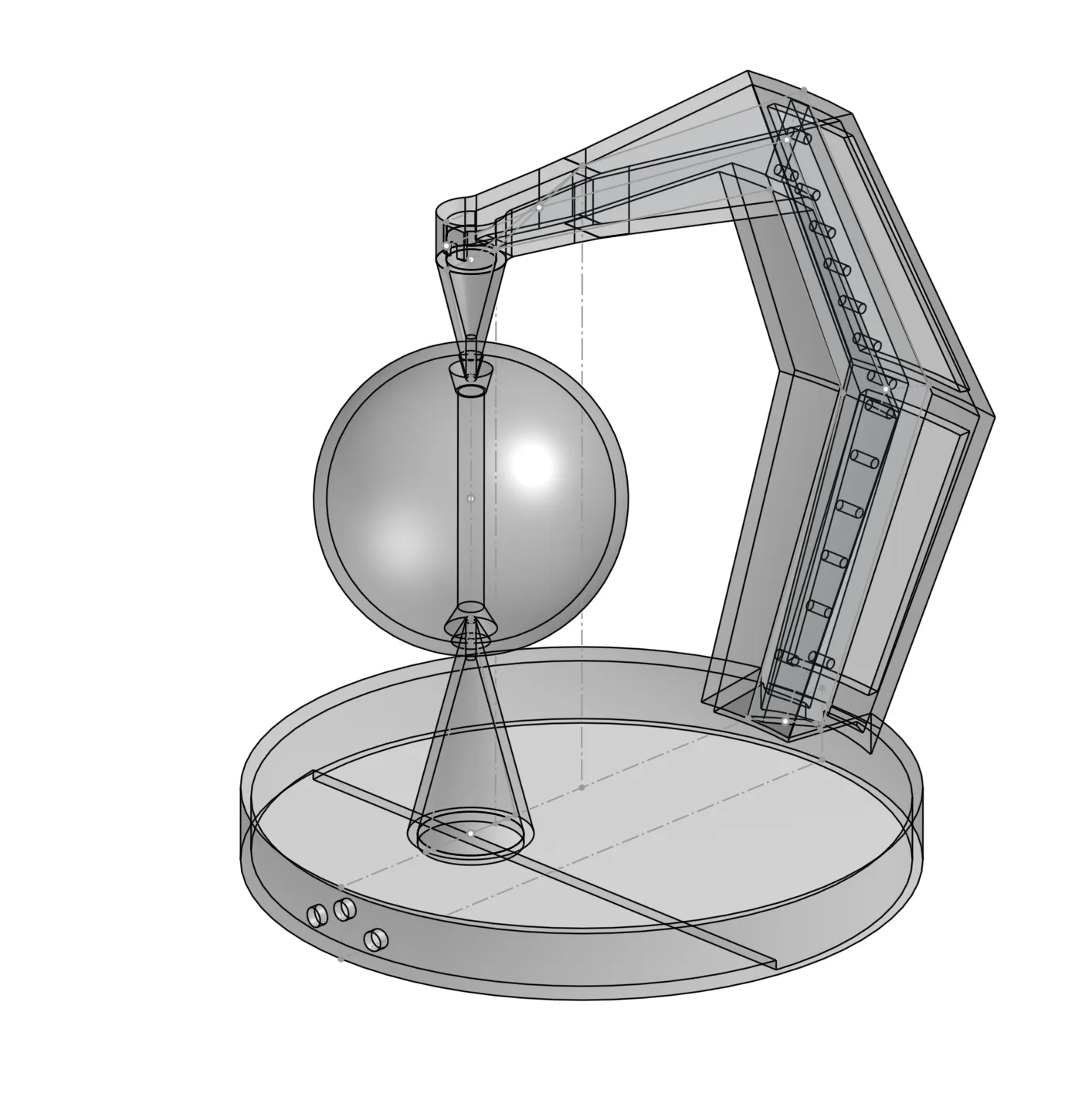
On the right is the first final draft of my CAD. I used this to start 3D printing parts, and even though it changed later, this version was about 90% complete. In the picture, the components are transparent because I wanted to visualize the diffused lighting and translucent 3D prints. My initial plan was to 3D print the entire sculpture as one part. However, I later found this wasn't possible because the part was too big for the printer, leading me to break the model down into smaller pieces. Also, note that my CAD at this time still planned on using standard LEDs, as I hadn't started working on the PCB yet.
Manufacturing (PCB and 3D Printing)
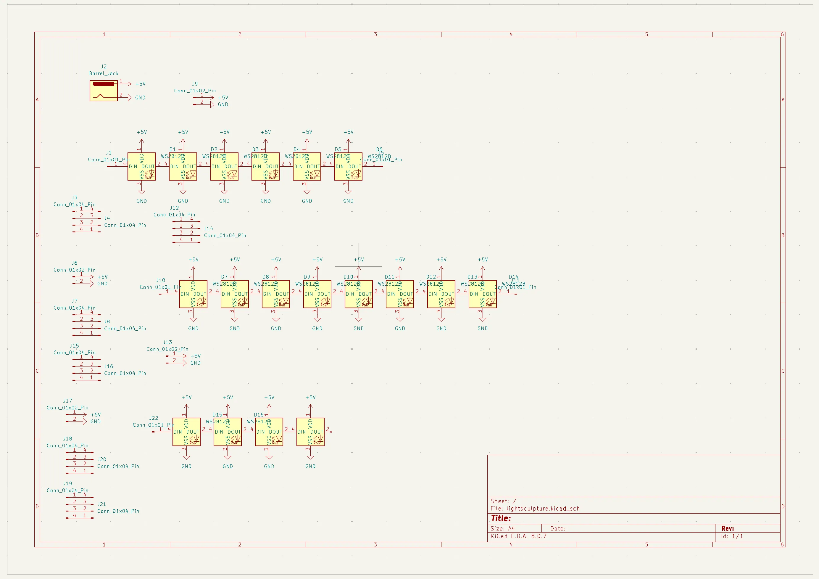
Here on the left, you can see the schematic for the PCB I designed. I did this because I wanted RGB lights so I could customize the color of the project. Instead of the 5mm LEDs that most people used, I integrated 18 WS2182B LEDs into my PCB. Along the way, I had to learn KiCad, a program for making PCBs. It was a very interesting process, and I know these skills will help me in the future.
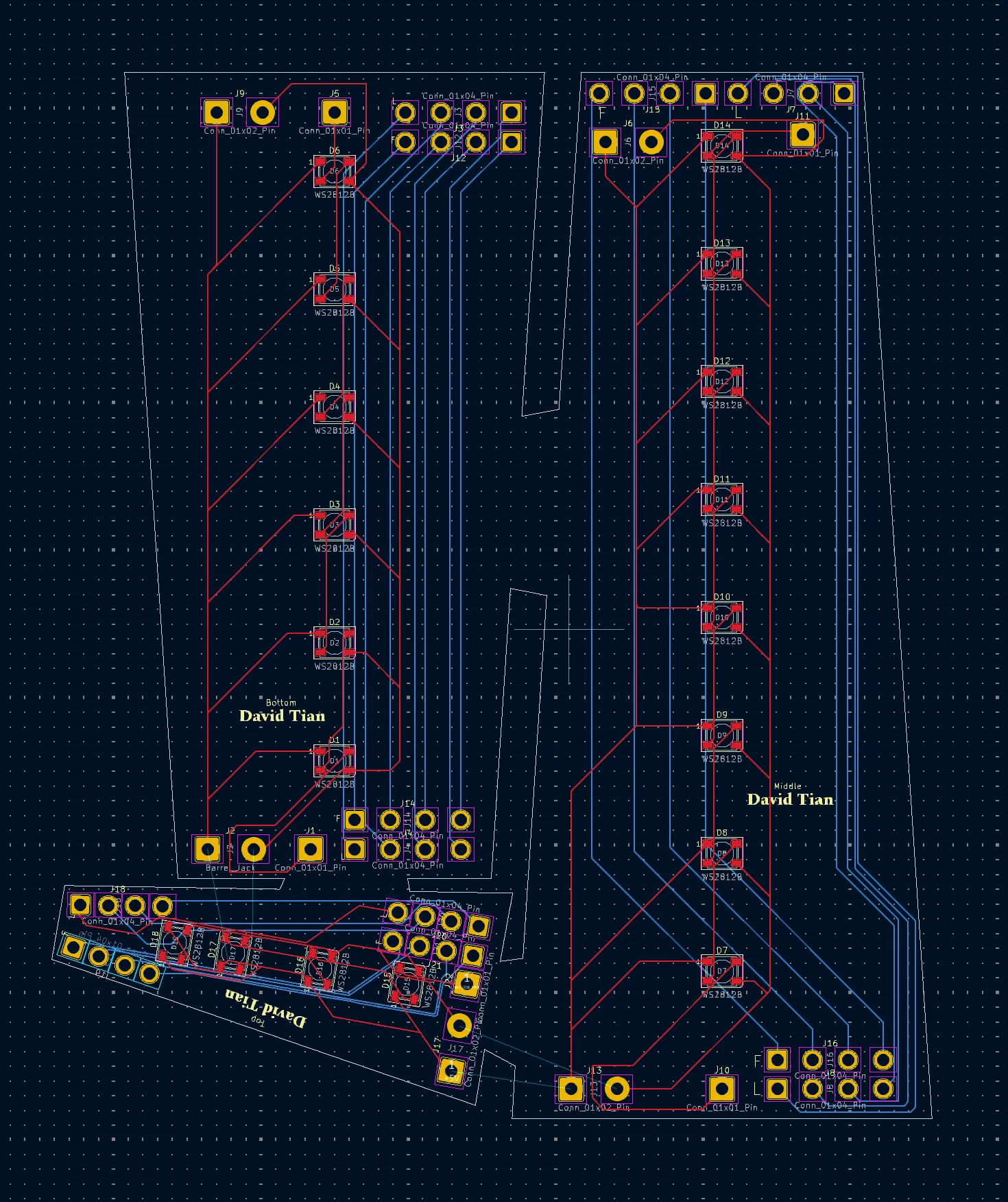
This is the PCB tab in KiCad. While the schematic tab (above) defines the logic, the board itself is defined here. It is in the PCB tab that you design the physical layout. You can see the exact dimensions I needed in the white outline. This layout actually consists of three boards connected together, which saved me $20 because the manufacturer charges more for multiple separate boards. I ended up paying $71 for the PCB, though most of that cost was shipping; only $30 was for the manufacturing itself.
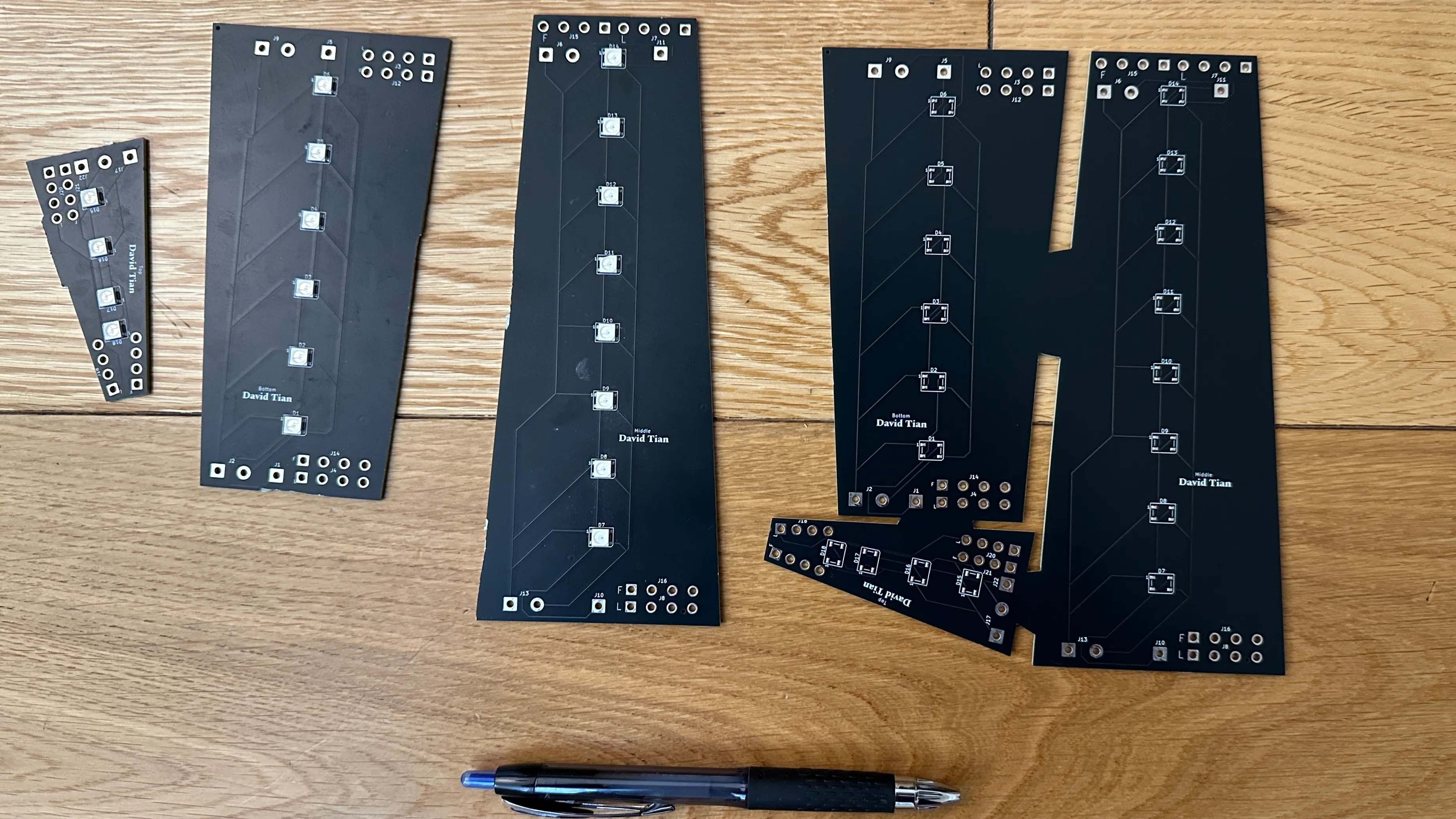
Above is the final PCB I ordered. The physical board was manufactured based on the design I created in KiCad. On the left, I have one set of the board with the LEDs soldered on, where I had already cut the parts to fit into the 3D-printed housing. On the right, you can see the board as it arrived, still in one piece.
For the rest of my project, I used 3D printing. I have included a couple of timelapses of the parts being printed below.
Soldering
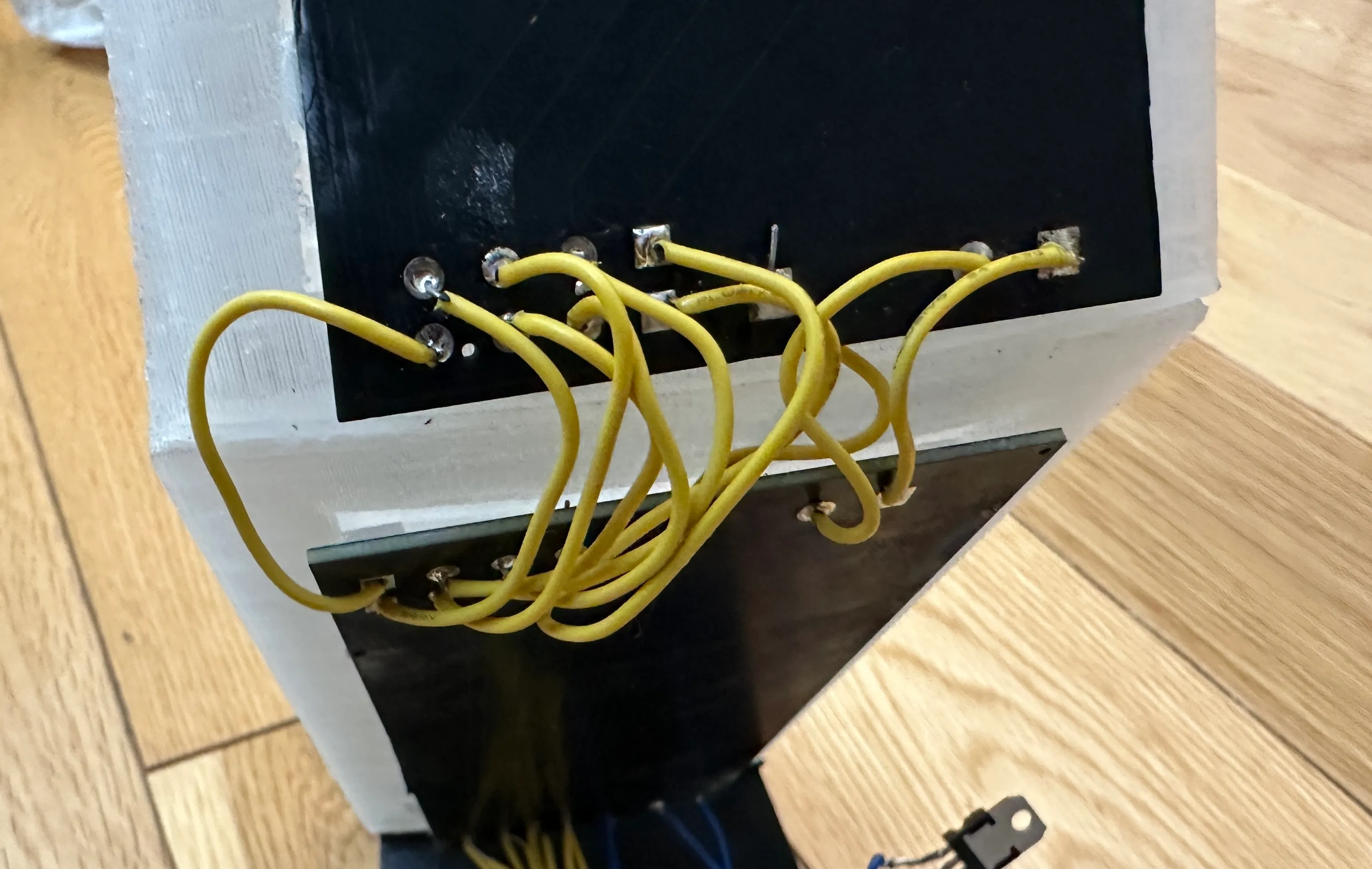
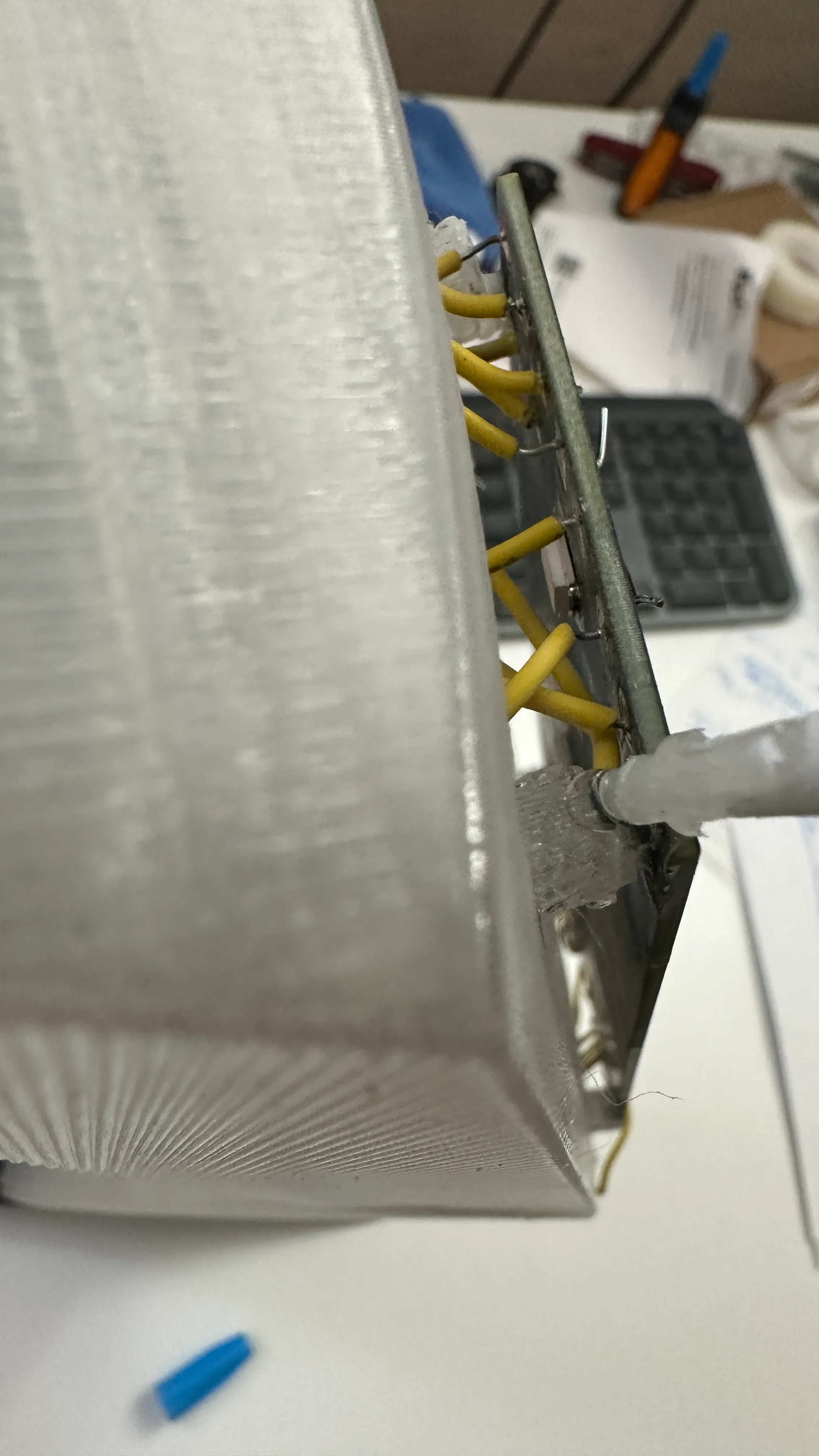
Because I integrated most of the electronics into a PCB, I didn't have much manual soldering to do. I did, however, have to solder the boards together. I purposely designed holes in the PCB to allow me to solder wires through them, similar to how a perfboard works. This wasn't difficult; on the left is an example of the soldered connections between boards.
Below is a video of me soldering. I am working on the voltage regulator, which ensures the correct voltage is fed into the PCB to prevent it from burning out. Overall, the soldering was relatively simple because I already have experience with it.
Assembly and Programming
To assemble the project, I used Gorilla superglue to connect the 3D-printed pieces. The process was simple: first, sand down the edges to create a better gripping surface, then apply the glue (I might have overdone it), and hold the parts together for a few minutes while they set. On the left is part of that assembly process.
This image shows me gluing the PCB onto the mounts I designed. You might notice I am no longer in the classroom; I was finishing this at home the day before the field trip.
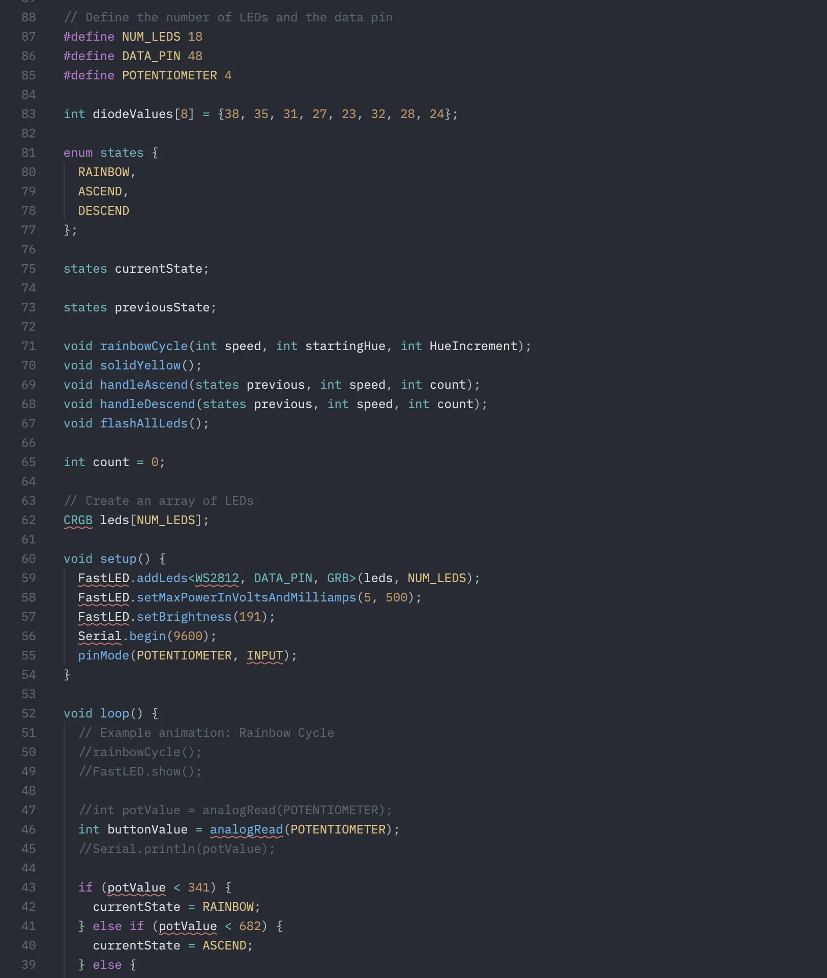
The code for the program was relatively simple for me due to my previous experience. The entire script took no longer than 30 minutes to write. To drive the 18 WS2182B LEDs, I used the FastLED library, which allowed me to individually control the brightness and color of each LED. This enabled cool patterns, such as an RGB rainbow. On the right is a picture of my code. I used VS Code instead of the Arduino IDE for its better Intellisense and the ClangD language extension. I built my code in PlatformIO, so the structure looks a bit different because I have to define functions before using them—a requirement of C++ that the Arduino IDE usually handles for you.
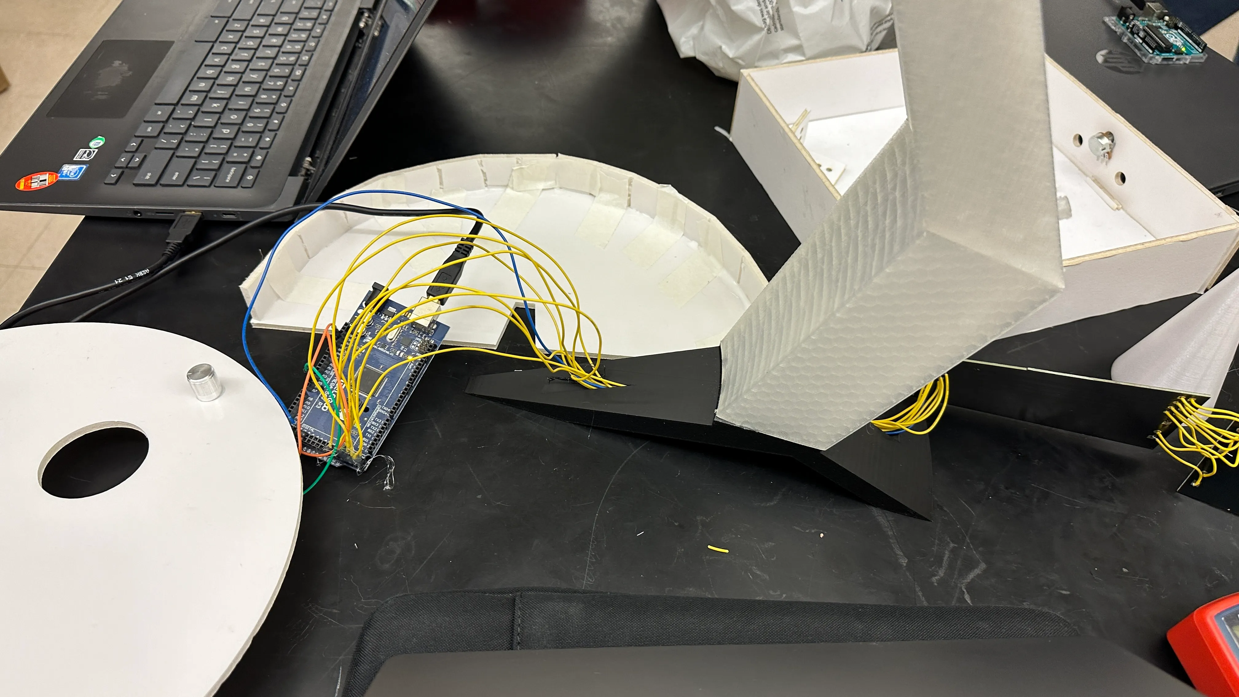
Once this was finished, the light sculpture was complete. The following day, I went on BART with the class to demo it at the Exploratorium. Below is a video of the final project. You can see the code running one of the programmed states. When the button is pressed, a new sequence triggers where light rises up the arm before the whole thing flashes. I used a button at the suggestion of Elan instead of a potentiometer.
Reflection
Overall, I really enjoyed this class and the process of making this light sculpture. Nothing was overly challenging, so I tried to go above and beyond by incorporating a custom PCB and complex 3D printing.
I did face several mistakes and troubles along the way. The most significant issue was designing the project so large that it couldn't be printed in one piece. This caused complications as I had to split the model and manage time constraints. Regarding materials, I should not have chosen PETG. I didn't realize there was transparent PLA until a week before the deadline. PETG is difficult to work with because it requires high bed and nozzle temperatures and must be printed slowly. My arm was estimated to take 7 days to print. You really have to monitor PETG closely, which didn't fit the tight schedule of this project. Additionally, I tried to save money on LEDs rather than buying higher-quality ones, which meant I couldn't drive them at full brightness or the speed I wanted. I also used an off-brand Arduino Mega 2560, which struggled with accurate loop timing and was very picky about power supplies; I actually had to power it from my laptop at the museum. My biggest mistake was running out of time to print the ball—an essential part of the sculpture—due to the slow PETG print speeds and Elan being absent for a week. Without Elan, I couldn't rely on laser cutting and had to 3D print everything. My main goal was ensuring the arm could stand without falling over, but this meant sacrificing the ball. To make it easier to explain at the time, I said I forgot it, but in reality, I was constantly queuing the printer to stay on schedule.
I was also able to collaborate with my classmates. When I heard Mateo wanted to make a Starship, I offered to 3D print it for him to ensure it looked its best.
Ultimately, the project was a success. The diffused RGB lighting turned out great, and I am pleased with how it looks both up close and from a distance. It is definitely more effective than standard LEDs would have been. I was able to adapt by splitting my model into 105 parts (up from the original 50) and using faster PLA or foamcore where necessary to solve production issues.